| tkCNC
Overview |
Screenshots |
Download |
Purchase |
FAQs |
Contact |
Online
Help |
Simulation window – Setup tab
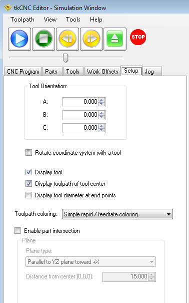
On setup tab in simulation window you can set how tools and tool path in simulation are displayed.
You can set:
- "Tool orientation" (A,B and C) – if tool is not in default orientation for selected machine you can rotate it (For a lathe machines use Tool setup angle under Tools tab)
- "Rotate coordinate system with a tool" – when checked, whole toolpath is rotated with a tool
- "Display tool" – toggles tool visibility in simulation
- "Display toolpath of tool center" – toggles visibility of tool center path (visible when G41 or G42 are used)
- "Display tool diameter at end points" – when checked, circle representing assigned tool diameter is displayed at each move end point
- With "Toolpath coloring" select one of five toolpath coloring modes:
- Simple rapid/feedrate coloring (default) - rapid and machining moves are displayed with different colors
- Different color for each tool – toolpath of each tool is colored by set tool color
- Different color according to feedrate – toolpath is colored according to feedrate value in CNC code (See also: Edit machine – Toolpath colors in 3D simulation)
- Only machining moves – only G1 (G2/G3) moves are displayed
- Only rapid moves – only G0 moves are displayed
- Part intersection – select this option to enable machining part intersection view (select plane type and distance from center)
See also: CNC program simulation/verification
tkCNC Editor - Your G-code editor