| tkCNC
Overview |
Screenshots |
Download |
Purchase |
FAQs |
Contact |
Online
Help |
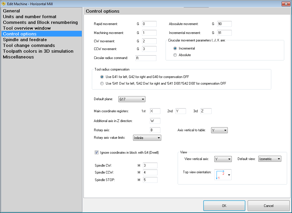
Edit machine – Control option

In this section you can define various options dependent of machine control:
- G movement commands (G0, G1, G2, G3)
- Circular radius command (how arc radius is defined in G2 and G3 moves)
- Incremental and absolute modes
- Mode for I, J and K registers for circular movements (older machines use absolute mode)
- Tool radius compensation mode (older machines use format e.g. G41 D10 to start tool radius compensation and G41 D00 to turn it off)
- Default plane (in most cases G17 for milling machines, and G18 for lathes)
- Main axis registers (default X,Y,Z)
- Additional axis for Z (some machines use W axis)
- Rotary axis – define register for rotary axis, if any, and define direction of rotary axis
- Rotary axis value limits – define if machine has infinite or limited rotary movement
- Ignore coordinates in block with G4 – if you use X register for G4 command this X will be ignored
- Spindle direction numbers (M3, M4, M5)
- View orientation (for 3D simulation):
- View vertical axis – define vertical axis for a machine (e.g. Z for vertical mills, Y for horizontal mills...)
- Default view – select default view on a scene when 3D simulation is started (Top, Front, Left, Right, Back, Bottom or Isometric)
- Top view orientation – defines how scene in 3D simulation is oriented according to top view
See also: Edit existing machine
tkCNC Editor - Your G-code editor